
In summer 2021 a subcontractor, AirPath, inspected NCC central HVAC air systems (that exchange air in large spaces and hallways) and found multiple issues in these units’ functioning and ventilation. Most of our occupied spaces rely on these central HVAC systems for air exchange. Importantly, even if the units were functioning at their design capacity, the units would not meet CDC recommendations for filtered and fresh air.
Note: this inspection did not include all the campus buildings, nor did it include any of the univent systems in offices and classrooms even in the inspected buildings.
Unfortunately, none of the units were functioning at their design capacity, and at least 9 units or their fans, could not be “energized” (turned on) for inspection. A visual inspection of their parts noted numerous issues such as: incorrectly sized filters, dirty filters, filters piled on the floor, holes in canvas, seals, ductwork, fans with cracked or missing belts, inoperable fresh-air dampers that were rusted closed or open, and dampers without actuators. Units that could be energized (turned on) generally had airflow below their design capacity, and often had incorrect, damaged, or missing parts. Of the ten buildings that could be tested, five were not able to bring in fresh air and another two brought in only 10% or less.
NCC buildings have two main types of ventilation:
Buildings inherited from the Air Force built in the late 1930’s. The ventilation for these is provided by windows and transoms above room doors with air exhausting through hallway windows. Central HVAC systems have been installed in some of these buildings that include supply and exhaust vents in the ceilings. Older buildings included in the AirPath report (below) are: S Building, N Building and M building.
Buildings constructed over the last 50 years have ventilation provided by units installed on exterior walls called “univents” with exhaust limited to how much of the room air can exhaust into the hallways where there are central HVAC vents in the ceiling. While univents draw in some fresh air, they also recycle a large amount of room air. If the fresh air damper inside the uninvent is broken, meaning it remains in the closed position, then even this fresh air supply is eliminated.
CDC/EPA Recommendations Ignored:
A “to do” list was generated by another contractor in August 2021 and given to the College. In January 2022, when CannonDesign released AirPath’s report, CannonDesign reported that all deficient equipment had been “addressed.” However, there is no verification for this assertion. Nor has there been a follow-up study by AirPath to verify that equipment is now functioning at capacity or to check the equipment that could not be inspected during its prior inspection.
Additionally, even if all HVAC units are now functioning at capacity, the college needs to consider what it means to move into an era when COVID-19 is endemic, if not pandemic. Particularly at a time when the country is eager to put away masks, we should bear in mind that even if our ventilation systems were currently functioning at 100% capacity, they do not meet the CDC/EPA recommendations that the level of air exchange should be greater than 6 air exchanges per hour to mitigate against COVID-19 and other airborne viruses. Meeting this recommendation not only requires enough fresh air or filtered air to be drawn into a room, but, as importantly, there needs to be enough exhaust capacity to remove stale air. Since no NCC building was built to the standard of 6 air exchanges per hour, to quickly and easily remedy this, the NCCFT has repeatedly requested the college use the HEERF (federal) funds to provide portable HEPA filtration units for all spaces currently in use and be sized to meet the CDC/EPA recommendations. In addition, it is important to note that the college’s response has been that masks are sufficient to protect the college population. We need to know, what will the college be doing going forward?
To ensure the safety of our students, faculty, and staff, the same study must be performed on the office and classroom HVAC air systems and airflow in spaces that have no HVAC systems. The degraded conditions AirPath discovered in the inspected systems is a good indication that conditions for classroom and office spaces are also neither adequate nor in good repair. It is critical the college employs competent HVAC technicians to repair and/or replace equipment, and the contractor needs to warranty its work. Furthermore, the College must establish routine inspections of these systems. This will not only ensure the systems are maintained but will result in vast cost savings.
Below is AirPath’s report with pictures. The report illustrates how horribly neglected these systems are. Again, documents provided by the college through our FOIL request indicate only a few repairs performed by August 2021 to identify problems, and many general statements of deficient equipment being “addressed.” It is important for the Reader to keep in mind that the below report was an incomplete inspection. It did not include any inspection or evaluation of the airflow of the univent systems in offices and classrooms.
HVAC SYSTEMS AIR SYSTEMS CONDITIONS ASSESSMENT REPORT
By AirPath
July 9, 2021
Cluster A:
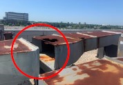
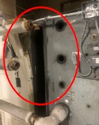
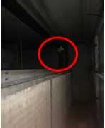
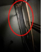
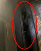
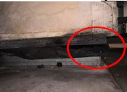
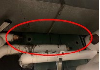
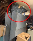
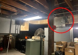
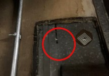
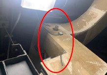
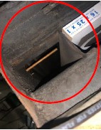
AC-1 is designed to supply 18540 CFM (cubic feet per minute). AirPath measured 12802 CFM. This unit is functioning only at 69.4% of design capacity. Even at 100% design flow for this unit would not meet the CDC recommendations for airflow (filtered and fresh). The air outlets AirPath measured have a total design airflow of 8355 CFM. AirPath measured 4246 at those outlets; thus, outlets function at only 50.8% of design capacity. There is a hole in the fan suction wall shown in the image on the right. Only one fan belt is installed, and the filters are very dirty which impedes performance. E-2 (the exhaust part) is designed to draw 56150 CFM. AirPath measured only 28344 CFM. The suction canvas is badly damaged and should be replaced. There are also holes in the discharge ductwork that should be patched as shown in the images below.
Cluster B:
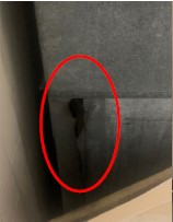
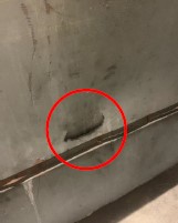
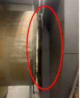
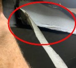
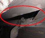
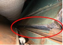
AC-2 is designed to supply 21170 CFM (cubic feet per minute). AirPath measured only 20022 CFM; thus, this unit functions at 94.6% of design capacity. The air outlets AirPath measured have a total design airflow of 10875 CFM. AirPath measured 9275 at those outlets. Thus, the outlets’ airflow is only 85.3% of design capacity. The top heating coil has been removed and the piping capped leaving holes in the unit sidewall that are unsealed. There is a large section of canvas missing at the heating coil inlet as well. The filters are dirty and should be replaced. E-4 (the exhaust part) is designed to draw 67670 CFM. AirPath measured only 39366 CFM. The discharge canvas is badly damaged and should be replaced as shown in the images. THERE IS A LARGE SECTION OF CANVAS MISSING BETWEEN THE COILS ON THE BACKSIDE OF THE UNIT. THE UNIT IS PULLING UNFILTERED MER (mechanical equipment room) AIR IN.

Cluster D:
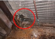
AC-4 is designed to supply 20595 CFM (cubic feet per minute). AirPath measured only 6800 CFM. This unit is functioning at only 33.0% of design capacity. The air outlets AirPath measured have a total design airflow of 6710 CFM. AirPath measured 1419 at those outlets. Thus, the outlets’ airflow is functioning at only 21.1% of design capacity. All of the chilled water valves are manually shut. There is no chilled water to cool the air supply for this building. The outside air damper has rusted shut and will not open. This unit is drawing 100% return air, bringing in no fresh air. The mixed air plenum access door is not well sealed. One belt has broken off the pulleys and the remaining three are badly cracked causing slippage. These should be replaced. E-29 (the exhaust part) is designed to draw 30590 CFM. Airpath measured only 19167 CFM. The suction canvas is badly damaged and should be replaced as shown in the images below.
Cluster E:
AC-5 is designed to supply 13100 CFM (cubic feet per minute). AirPath measured only 11734 CFM. This unit is functioning at 89.6% of design capacity. The air outlets AirPath measured have a total design airflow of 6330 CFM. AirPath measured 5705 at those outlets. The air outlets are at 90.1% of design capacity. The outside air damper actuator pneumatic line was found disconnected. AirPath reconnected the line and the damper opened. The supply discharge canvas is damaged and there is a patch on the supply discharge duct that is not well sealed. The filters are dirty and should be replaced. E-38 (the exhaust part) is designed to draw 44770 CFM. AirPath measured 17911 CFM. The discharge canvas has a large hole in the bottom and should be replaced. See images below.
Cluster F:
AC-6 is designed to supply 38190 CFM (cubic feet per minute). AirPath measured only 26184 CFM. This is only 68.6% of design capacity. The air outlets AirPath measured have a total design airflow of 6185 CFM. AirPath measured 5080 at those outlets. This is 82.1% of design. The return air damper was found fully closed. This unit was tested at 100% outside airflow. The filters are dirty and should be replaced. The fan belts are loose and should be tightened. Both the heating and cooling coils are dirty and should be cleaned. All of these issues are affecting performance.
Life Science:
AHU-1 is designed to supply 25550 CFM (cubic feet per minute). AirPath measured 26327 CFM. This unit is over-performing and the VFD (controller of speed) can be reduced to meet design airflow. The BMS is showing a discharge airflow of 0 CFM. The BMS is also showing an outside airflow of 18065 CFM. These are with the unit in Economizer mode (100% outside air). Its system of sensors and air balance are mismatched: The outside airflow monitoring station sensors are located in the middle third of the outside air intake. This does not capture an accurate account of the outside air velocity. Also, the area programmed into the monitoring station is 22 ft2, but the area of the sensor location is around 38-40 ft2. The filters are dirty and should be replaced. The return fan is designed to produce 25550 CFM. AirPath measured 21361 CFM. AirPath tested several VAVs connected to AHU-1. The two that serve classroom 221 are underflow. AirPath measured 1364 CFM & 1433 CFM where both boxes are designed for 1920 CFM. TU-3-9 & 11 are underflow as well. They are designed for 525 CFM each and AirPath measured 466 & 463 CFM respectively. TU-3-12 is over design airflow. The box is designed for 500 CFM and AirPath measured 649 CFM. EF-9 A,B,C serves the lab fume hood exhaust. The three fans run together. The system has energy recovery and filters at the intake. The filters are dirty and damaged and should be replaced. The fans are designed to draw 24050 CFM together. AirPath measured 24915 CFM. The fume hoods in classroom 219 do not adjust based on the sash position. The Tek-Air FVC-2000 controllers for these four hoods remain at 90 FPM regardless of sash position. The exhaust box that serves classroom 219 needs to be recalibrated. AirPath measured 1620 CFM, but the box is designed for 700 CFM. All of the fume hoods in classrooms 219 & 221 are over the design flow of 675 CFM.
Tower T:
AC-2 was found with the fan belts broken and cracked. The motor is running but there is nothing driving the fan. The same is true with RF-2, the return fan for AC-2. There are also several holes in the unit sidewall that are not sealed. (No pictures were included in the report.)
Library:
AC-2 is designed for 19925 CFM (cubic feet per minute). AirPath measured only 14667 CFM. The outside air damper was found to be rusted closed and would not open. Thus, the unit is drawing 100% return air and no fresh air. One filter is missing. E-2 is designed for 13720 CFM. AC-2 is drawing 100% return air; the unit is overpowering fan E-2, which is drawing more air from the return and MER (mechanical equipment room) due to the suction canvas being damaged. It should be replaced. One belt is broken and should be replaced.
PE Building P:
AC-1 is designed to supply 31100 CFM (cubic feet per minute). AirPath measured only 28583 CFM. The filters are dirty and should be replaced. The return fan (E-1) has one belt that is broken. The fan is being driven by only one belt. The suction canvas is damaged and needs to be replaced. AirPath could not measure airflow for this fan.
HV-1 does not energize. AirPath was told by NCC facilities that the unit has not run in many years and could not be brought online during Hurricane Sandy relief efforts. AirPath was advised not to test.
HV-2 is designed for 70000 CFM. Airpath measured only 52967 CFM. The return air damper is rusted in the full open position and does not close. The return fan (E-12) was not running until facilities put it into ‘Hand’ mode. This fan is designed for 63000 CFM. AirPath measured 57082 CFM. There is a large hole in the bottom of the suction canvas. AirPath measured the airflow at the outlets for both HV-2 & E-12. AirPath measured 33896 CFM at the outlets for HV-2. There may be air gaps in the ductwork that are not easily noticed. AirPath measured 38503 CFM at the outlets for E-12. The fan is drawing air in from the MER through the large hole in the bottom of the suction canvas. The following information on the PE building’s exhaust fans was taken on 6/18/21; since that time facilities made some repairs, but AirPath has not been directed to return to inspect any of the following equipment. Fan E-2 is not energized. AirPath could not test. The fan E-4A does not exist. It is not shown on the drawings nor is it installed in MER-2. The mechanical schedule has a note that states this fan is an architectural alternate and would replace E-4. Fan E-4 had a cracked belt. It is designed for 3700 CFM. AirPath measured 3344 CFM. Fan E-5 is not energized. AirPath could not test it. The motor for fan E-6 is energized; what is visible is that the belt has broken off the pulleys, and there is nothing to drive the fan currently. Either 1) A-27 or 1) 4L-290 belt should be installed before AirPath can test this fan. The same is true for fans E-7 & E-8 which need 1) A-55 belt and 2) b-96 belts respectively. E-9 has a large hole in the bottom of the suction canvas as shown in the image. AirPath measured 16900 CFM where the fan is designed for 36000 CFM. EF-10 & 11 are not energized. AirPath could not test these fans. EF-13 is designed to exhaust 49200 CFM. AirPath measured only 11926 CFM. The damper at the discharge of the building is rusted in a mostly closed position and will not open further, limiting the intake of fresh air. E-14 has the same issue as E-6, 7 & 8. 2) B-103 belts need to be installed. E-15 is designed for 17600 CFM. Airpath measured 10347 CFM. E-16 is not energized. AirPath could not test. E-17 also has no belt installed. 1) A-30 belt is needed. E-18 is not energized. AirPath could not test. E-19 has no belts installed. The belt size needed could not be identified. E-20 is not energized and has no belts installed. The belt size could not be identified.
G Building:
AC-1A is designed for 4800 CFM (cubic feet per minute). The outside air damper is fully closed, so no fresh air is drawn in. The damper actuator is functional, but the linkage is broken. The return air damper is fully open and functional. AirPath measured 3985 CFM from the return fan discharge but after the spill air duct. AirPath measured airflow at the outlets in the ceramics studio. AirPath measured 2504 CFM at the supply outlets that have a total design of 4720 CFM. This is only 62.8% of the flow measured at the unit. AirPath also measured 276 CFM at the only return outlet for this system. This means that the unit is drawing 3709 CFM through the spill air duct.
AC-3 is a hot deck/cold deck dual duct unit designed for 19000 CFM. AirPath measured 13018 CFM at the unit. The outside air damper is in two positions. One side is open 30% and the other side is open 10%. There may be a leak in the pneumatic line between the two dampers as they both open fully when commanded. There is air leaking at the cold deck access door. The fan suction vortex damper is mostly closed. There is a hole from corrosion in the heating coil as shown below. AirPath tested several VAVs connected to AC-3 on the first floor. These boxes are controlled based on room temperature and the BMS is constantly changing setpoint and damper position to meet temperature. Several of these boxes are dual duct and therefore have two damper positions and airflow sensors. The airflow shown on the BMS for most of these boxes do not align with what was measured in the field.
AirPath also tested EF-5 which serves the toilet exhaust for this building. Only one belt is installed. The fan is designed for 2300 CFM and AirPath and measured only 1706 CFM. Airpath read all but one outlet on this system. The total airflow measured at the outlets is 1156 CFM. This fan was the only fan running on the roof of this building. EFs 1, 2, 6, 7, 8, 9, 10, 12, 17, 35, 36, 37, 38, 40, 41, 42, 43, 44, 49, 50 & 52 were all not running during the time of testing. EFs 4 & 39 had their disconnects on the roof turned off. EF-3 also had the disconnected turned off, but the ductwork had rusted to the point where it was in pieces as shown in the picture on the right above. See pictures below.
College Center (CCB):
AC-7 is designed to supply 29185 CFM (cubic feet per minute). Airpath measured 35513 CFM at multiple locations at the unit. This unit is over-performing; the BMS (building management system) is not controlling the system properly. The BMS for this unit shows a total flow of only 3994 CFM. AirPath measured a return airflow to the unit of 7187 CFM in contrast to the BMS measurement of a return airflow of only 482 CFM. Some of the filters are not installed that should be. The hot deck coil has been disconnected and there are holes in the unit sidewall where the piping would connect. The back panel on the top of the unit at the hot deck section has separated. There is a large amount of air loss. See pictures below. There are also two holes from corrosion in the bottom left of the heating coil.
AirPath tested VAVs connected to AC-7 on the second floor of College Center. These boxes are controlled based on room temperature and the BMS is constantly changing setpoint and damper position to meet temperature. One of the boxes is a dual duct and therefore has two damper positions and airflow sensors. The airflow shown on the BMS for these boxes does not align with what was measured in the field. AC-10 is designed to supply 8850 CFM. AirPath measured 8714 CFM. The BMS for this unit shows a total supply airflow of only 617 CFM. AirPath measures a return airflow to the unit of 2774 CFM. The BMS shows a return airflow of only 752 CFM. The unit is overpowering the return fan and drawing air in through the spill air duct. The outside air damper does not close fully. Some filters are not installed that should be. The fan belt is slipping and should be tightened. There is a small hole in the hot deck discharge canvas. There is a small hole from corrosion in the bottom left of the heating coil.
AirPath tested VAVs connected to AC-10 on the first floor. These boxes are controlled based on room temperature and the BMS is constantly changing setpoint and damper position to meet temperature. All of the boxes tested are dual duct and therefore have two damper positions and airflow sensors. The airflow shown on the BMS for these boxes do not align with what was measured in the field. EF-20 does not energize. The disconnect at the roof was found off. When AirPath turned the disconnect to ‘ON’ the motor did not start. EFs 24, 25 & 26 were not running during the time of testing. EF-27 would turn on and off intermittently. AirPath could not test EF-27 in that condition. AirPath found the motor for EF-21 running with no fan belt. The belt had broken off. AirPath replaced the belt and re-aligned to pulleys so the fan would run. AirPath calculated the fan is drawing about 1240 CFM from the toilets based on the Greenheck fan curve and measured rpm and pressure readings.
N Building:
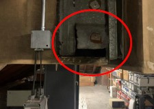
AirPath went to test the attic air handling unit to find that it would not energize. AirPath was told by Nassau Community College Facilities that the unit is powered off for summer shut down. It cannot easily be brought online to test. There are 1″ filters installed in the 2″ filter track. The unit may pull the filters off the track when it is energized. There is a large opening for filter access and below the filter rack where unfiltered air can enter the unit and be sent into the space. There is a hole in the outside air duct sidewall. There is an outside air damper that has been abandoned in place. The actuator has been disconnected and the damper is rusted fully open. The access door by this damper is missing. The main unit is heating only. There is also a small upright DX unit tied into the supply ductwork, which should serve for cooling the space. It is also turned off and cannot be energized. Several of the pneumatic lines for the main unit have been disconnected. See pictures below.
S Building:
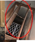
AirPath went to test the attic air handling unit to find that it would not energize. AirPath was told by Nassau Community College Facilities that the unit is powered off for summer shut down. It cannot easily be brought online to test. There are 1″ filters installed in the 2″ filter track. Half of the filters have been taken out and are on the floor. The filters are stacked together to fill the rack. This can cause an added restriction to the unit. The filter rack opening is not sealed. The outside air damper is rusted and 90% closed. The access door by this damper has fallen off and is on the floor. The main unit is heating only, and there is also a small upright DX unit tied into the supply ductwork. This small DX unit should serve for cooling the space. This unit is also turned off and cannot be energized.
M Building:
Airpath could only find two units in the building with the help of NCC Public Safety The two units AirPath inspected were found on the 3rd floor of this building in the back mechanical spaces. AirPath did not receive drawings that show the unit schedules or the ductwork showing connected outlets. AHU-3 was found in the mechanical space behind office 307. The unit was found running. AirPath could not get a total supply airflow measurement at the unit. Airpath took airflow readings at nine outlets in the space for offices 300 – 307. The total airflow at these outlets was 4538 CFM, but the outlet in office 301 measured 0 CFM. This outlet may be connected to a different unit in the building that is not running. AirPath found the outside air damper fully closed. There is no actuator for this damper to open and close the damper. AirPath manually opened this damper and took a reading across the return air intake to get an outside airflow of 1185 CFM. AirPath found that the filter access panel has no enclosure. There is also an opening in the outside air duct where piping has been run. The fan belt was found to be loose and needs to be tightened. AirPath found a unit in the mechanical space behind office 314. This unit is identical to AHU-3 but has no delineation as to which unit it is. The unit would not energize. The thermostat for the unit lists it as being in ‘AUTO’ mode. The space temperature was 83.5 degrees, and the unit would not run. AirPath attempted to adjust the thermostat, but this did not turn the unit on either. AirPath could not test this unit. The outside air duct was found to have a manual balancing damper installed as the outside air damper. There is also no actuator for this damper, so the damper would not open and close. The filter access panel for this unit also has no enclosure.
One Response
HOLY CRAP!
This is beyond neglect, this is criminal.